VISI Analysis
VISI Analysis - Solutions for the validation & preparation of model geometry
When working with imported data, the quality of the model is an important consideration. Finding potential problems at an early stage within the project will greatly simplify the task of the designer and generate huge time savings further along the design process.
Features at a glance:
- Automatic recognition of design changes
- Model curvature and radii checking
- Thickness Analysis
- Dynamic face analysis
- Draft angle visualization
- Core & cavity model separation
- Controllable surface edge simplification
- Multiple split line calculations
- Dynamic parting face creation
- Model validation and geometry cleaning
- Redundant data and sliver face detection
- Tolerance control for surface edges
- Animated mold opening sequence
Automatically check for design changes. The model comparison tool provides the ability to load two models (solid or surfaces) and check for design changes. Any model deviations are highlighted using a new color and using the transparency slide bar, it is possible to switch the visibility between either models to quickly identify the design changes. A second option will again identify the design changes, using a set of user-defined distance parameters; it is possible to see the physical distance changes between the two models. Automatic extraction of the model differences makes it quick and easy to apply design changes to existing data.
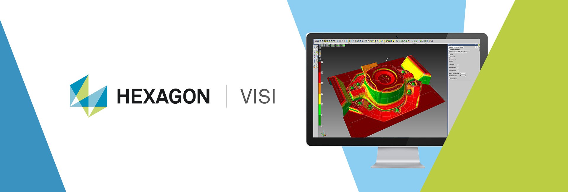
Draft angle and radii checking. Draft analysis is where to start on any model to quickly validate the molding feasibility. Finding potential design issues at this stage will generate huge time savings. Simply select the molding direction and the model will be rendered using user-defined color draft zones to easily identify problem conditions. The graphical interface can also be used to highlight the model curvature and max / min radii.
Thickness Analysis. A very important tool for the molding industry. This tool graphically displays the model thickness providing valuable information for potential gating positions, rib criteria and cooling channel locations.
Edge conditions. When working with imported data, the geometry edge conditions can have a major effect on the model quality and be an important key to a successful project. VISI Analysis contains tools to interrogate the model topology for both editing and simplification of the surface edge and tangency conditions.
Graphically split a model into core and cavity. Multiple analysis and separation tools are available to interrogate the model and gather the surfaces required for the relevant core, cavity, undercut or side moving zones. Undercut or slide features can be grouped and dynamically translated along a movement axis to represent the mold opening sequence. The animation can be saved as an external XML file and re-run at any point proving an invaluable tool in helping to explain the complete working of the mold tool. The split line manager provides 3 different routines for finding the optimum split line. Using the interface it is possible to interact with the computer generated result and modify it to suit your own design requirements. It is possible to extract the split line as curve geometry or automatically separate the model into the relevant core, cavity or side moving zones.
Parting & shut off faces. The creation of the parting and shut off faces are often one of the most time consuming and difficult tasks that a designer can face. A comprehensive suite of surfacing tools and a split plane manager combine to create a powerful tool for the generation and management of the most complex parting faces. Externally created surface sets such as intricate shut off conditions can be imported into the split plane manager and combined with extruded, offset, ruled, connection and patch surfaces to generate the parting geometry. Using the split plane tool it is also possible to automatically create the core and cavity models using the part geometry. Providing help and removing the laborious tasks will release the designer to fully utilize their experience and maximize their productivity.
Model validation and cleaning. Powerful model clean-up tools are available to check data for redundant geometry. Duplicate geometry will be automatically highlighted, extracted and moved to another layer. Sliver face recognition will analyse the model and detect any potential problematic faces based upon a user-defined surface area. Automatic removal, healing and sewing will maintain the solid topology and guarantee data consistency. Graphical solid interference checking and model validation for corrupt data, geometry faults and trimming conditions will ensure the best possible result.
Seed faces. The seed faces tool provides the ability to select a single or multiple starting faces and automatically detect any flowing surfaces from the reference face using a user-defined angle threshold. This tool is particularly useful and a very fast way of extracting water jackets or separating geometry into A & B surface sets.
Tip Data. If working with geometry in 'car-line' or managing data between multiple origins, tip data greatly simplifies the task of moving information from 3D model space to your working origin. All movements between origins can be extracted and output to a report file for future reference and project documentation.
Surface Analyser. An information tool that will provide relevant face data as you dynamically move the mouse over the model. Without doubt, the fastest way to check draft conditions, trimming loops or fillet radii.


